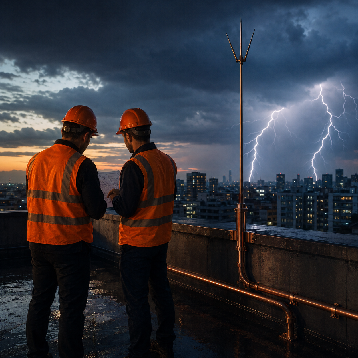
The ESE lightning conductor is the most widely applied lightning protection system in Turkey — yet it is not the method recommended by the national standard. This contradiction comes up in the field every day and, when it is not handled properly, it produces systems that comply with the regulations but are weak in reality.
In Turkey, the lightning protection of structures and facilities is defined by the TS EN 62305 standard. This standard requires the protected points to be determined by the rolling sphere method following a risk assessment, together with the Faraday cage approach that arises from integrating the air terminals by the mesh method. The ESE conductor, on the other hand, is defined under the French national standard NF C 17-102 and does not appear in TS EN 62305.
Even so, ESE conductors continue to be requested in the specifications of public institutions and in the fire regulations. Our position at Yılkomer is clear: if the specification calls for an ESE conductor, we install one — but we reinforce the system with the measures the standards require.
What Is an ESE Lightning Conductor and How Does It Work?
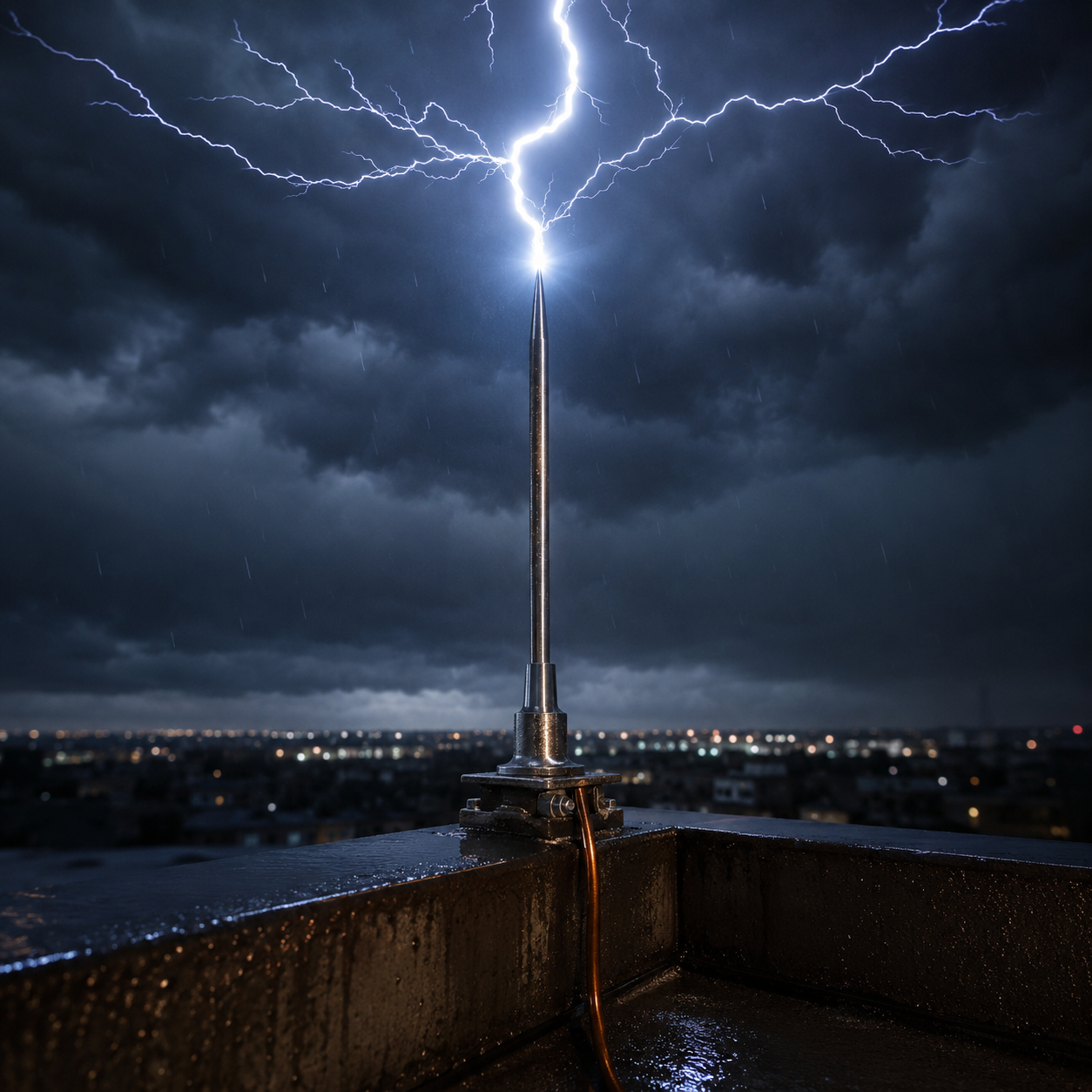
Unlike a conventional air terminal, an ESE conductor is an air termination system that carries a triggering mechanism inside its head. Its purpose is to initiate the upward leader earlier, thereby attracting the lightning to itself and bringing a larger area under protection from a single point.
In the past this function was provided by radioactive materials; after radioactive conductors were banned, their place was taken by “active” heads containing components such as coils and piezoelectric crystals, known in the international literature as ESE (Early Streamer Emission). Every ESE conductor on the market today belongs to this group.
Why Are ESE Conductors Debated? Four Key Points
The protection radius claimed for ESE heads is not defined within the scope of IEC 62305. The system rests on the French national standard NF C 17-102. This does not mean the product cannot be used; it means that its protection performance cannot be verified by the international calculation method.
In a Faraday cage the protection can be calculated and verified from the rolling sphere and mesh geometry. With an ESE conductor, the protection radius rests on the manufacturer's declaration. Because there is no chain of calculation the engineer can verify, the designer must bring in a risk assessment of their own.
Lightning does not always arrive along a vertical path. IEC 62305 places particular emphasis on protecting the side faces of the upper 20% of structures taller than 60 m by the mesh method. NF C 17-102, on the other hand, prescribes no measure against lateral strikes. In tall structures this difference becomes critical.
Because an ESE head is mechanically simple to manufacture, poor-quality production is widespread on the market. A head turned on a lathe, with no working mechanism inside it, is in our view no different from an ordinary air terminal — but its price and its claim are. At a facility that has to be protected, product and system quality must be kept at the highest level.
If the Specification Calls for an ESE Conductor: Six Rules for Correct Installation
When an ESE conductor is chosen, the installation decisions that strengthen the system are as follows:
- Do not leave the corner points unprotected. Lightning favours sharp points. Add air terminals at the roof corners to build a system integrated with the ESE conductor, and close off the areas left exposed to strikes arriving from the side.
- Observe the separation distance (s). The calculated separation distance must be maintained between the down conductor and the metal parts inside the structure. Where it cannot be maintained, an insulated conductor must be used.
- Install two symmetrical down conductors. Running two conductors down side by side, common though this practice is, has no basis in the standards. The down conductors must be symmetrical, on two different faces of the structure; this splits the potential in the ground and allows faster dissipation.
- The down conductor does not have to be solid copper. Provided the separation distance is maintained, AlMgSi alloy down conductors may also be used; special insulated conductors are preferred on routes where the distance s cannot be achieved.
- Bond the earthing into the equipotential system. The earthing of the ESE conductor must always be brought to the same potential as the facility earthing. Using an arc-extinguishing isolating spark gap at this connection point provides a safer junction.
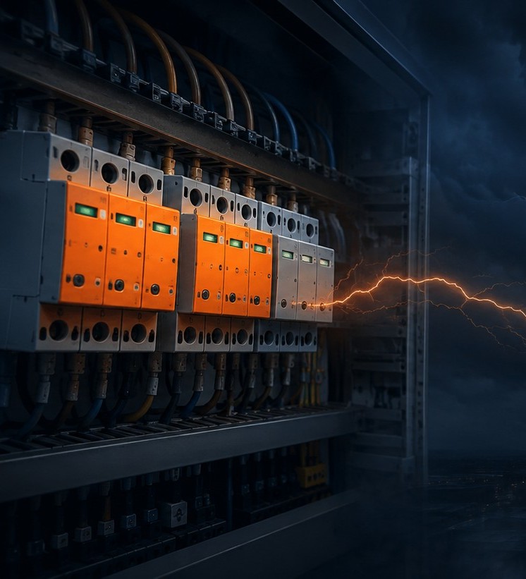
- Do not skip the low-voltage SPD system. Whatever the external lightning protection system may be, coordinated SPD protection must be applied at the distribution boards. A strike to the facility can put equipment out of service even when the external system does its job.