A solar power plant is, by definition, an investment exposed to lightning: a system in open terrain, spread over a wide surface, built on a conductive mounting structure and containing kilometres of DC cable. Add to this the fact that uninterrupted generation is the plant’s only revenue-producing activity, and protection stops being an option and becomes part of the investment.
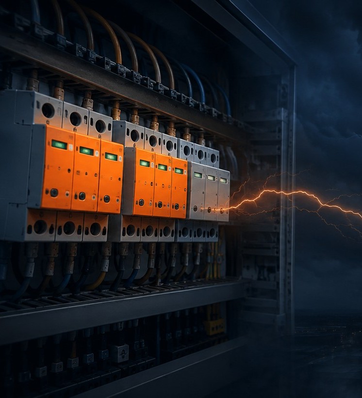
In solar plants the damage is usually caused not by a direct strike on the site, but by the voltage induced in DC cable loops by a nearby strike. Inverter boards, string monitoring units and communication systems are sensitive to these surges; the fault appears not on a single panel but as lost generation across an entire block.
In solar projects Yılkomer manages the entire process — from risk assessment and equipment selection through to installation and periodic inspection.
Five Factors That Shape Protection Design in a Solar Plant
1. Air Termination System and the Shading Trade-off
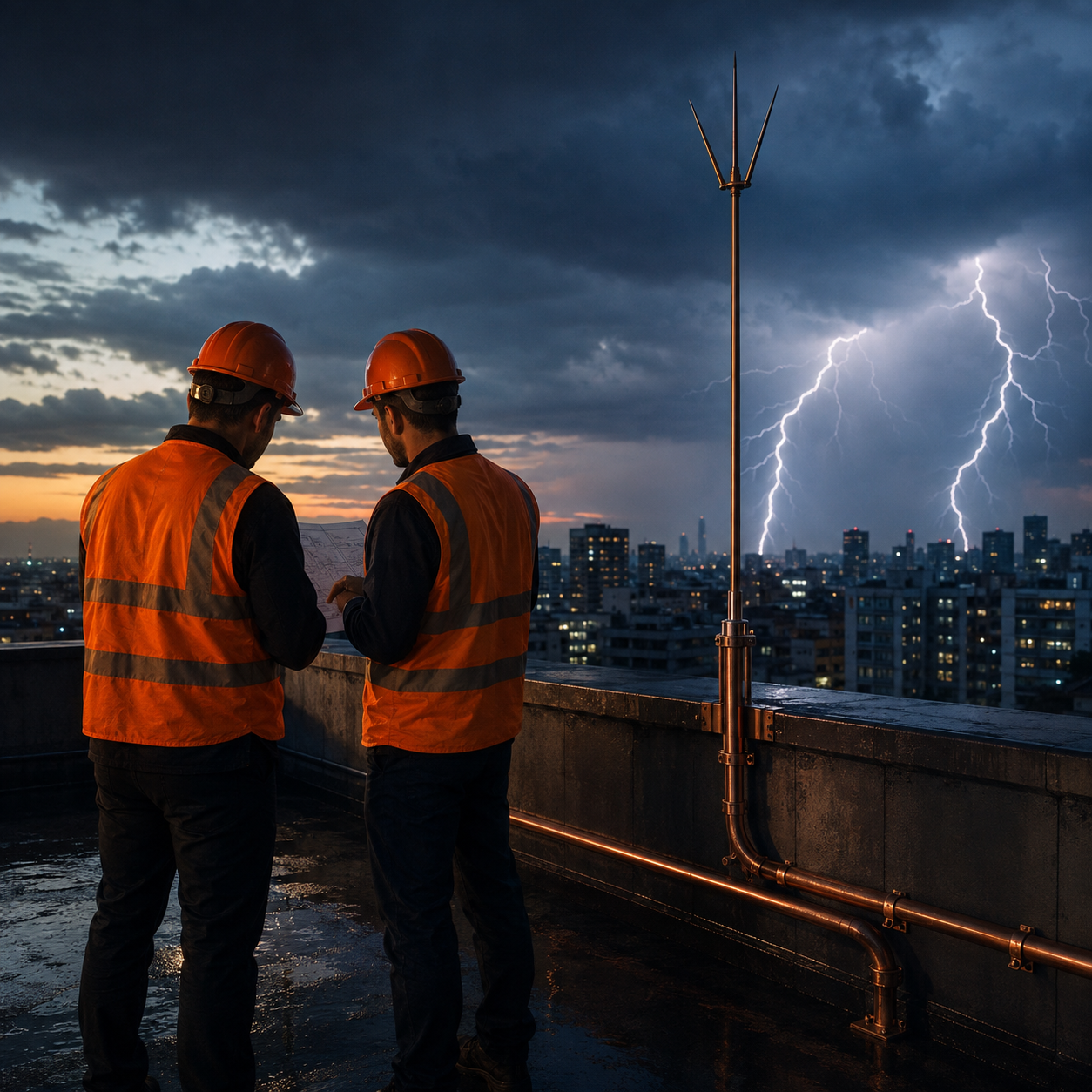
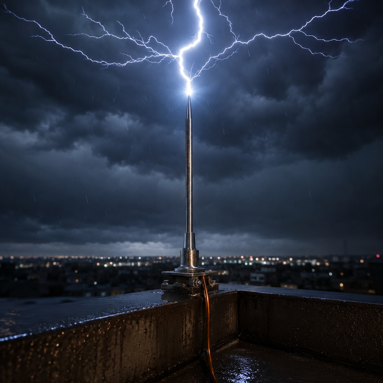
Protection against direct strikes is provided by independent air termination masts that do not touch the panels. However, every mast is also a source of shade, and shade means lost generation. The task of the design is to find the number and position of masts that deliver the required protection radius while keeping shading to a minimum. This is an optimisation problem solved by calculation; masts placed by eye leave either unprotected areas or permanent generation losses.
2. Separation Distance (s)
The calculated separation distance between the air termination system and the panel mounting structure must be maintained. Where it cannot be achieved, an insulated down conductor is used. If this distance is ignored, the current striking the mast flashes over to the nearest metal structure and enters the panel array directly.
3. The Risk Specific to the DC Side
In DC circuits an arc does not extinguish itself as readily as it does in AC. For this reason a DC SPD must be selected taking into account its maximum continuous operating voltage, the string open-circuit voltage and the temperature correction. A wrongly selected DC SPD creates a fire risk instead of providing protection — it is one of the known causes of solar plant fires.
4. Cable Routing and Loop Area
The further the positive and negative conductors of a string cable are separated, the larger the loop area between them; this directly increases the induced voltage. Running the conductors together and along a route close to the structure is one of the most effective measures that can be taken without buying a single product.
5. Earthing and Corrosion
The mounting structure is usually aluminium or galvanised steel, while the earthing conductor is often copper. Where these two metals are in direct contact, galvanic corrosion begins and the connection loses its function over the years. The right transition components and connection method determine continuity throughout the site’s 25-year life.
Product and Equipment Groups
- DC SPDs — At string and combiner box level, types suited to PV characteristics.
- AC SPDs — Coordinated protection for the inverter output, transformer building and switchyard.
- Signal and communication SPDs — For string monitoring, RS-485 and Ethernet lines.
- Isolated air termination masts — Independent mast solutions that provide protection without touching the panels.
- Isolated air termination masts — Independent mast solutions that provide protection without touching the panels.
- Structure bonding components — Corrosion-resistant clamps for bonding the mounting profiles and module frames.
- Earth electrodes and conductors — Ring earthing and driven electrode applications.
- Exothermic welding equipment — Permanent, corrosion-proof joints for underground connections.
- Equipotential bonding bars — Collection points in inverter and transformer buildings.
Additional Considerations for Rooftop Solar Systems
For systems installed on the roof of an existing building the picture changes:
- Integration with the existing lightning protection system — The panels must remain within the protection volume of the existing air termination system.
- Separation distance — The distance between the panel structure and the down conductors must be recalculated.
- Roof penetrations — An SPD and an equipotential bonding connection are required at the point where the DC cables enter the building.
- Fire safety — The consequences of a DC arc on a roof are far more severe for the building than they are on a ground-mounted site.
How We Work
- Site and project review. The layout plan, single-line diagram, structure type and soil data are evaluated.
- Risk assessment. The protection level is determined according to TS EN 62305-2.
- Air termination system optimisation. The protection radius and shading are calculated together to produce the mast layout.
- SPD coordination. The DC, AC and signal sides are designed as coordinated stages.
- Earthing and equipotential bonding design. The mesh geometry and connection details are determined according to the soil resistivity.
- Installation, measurement and reporting. Post-installation measurements are carried out and a periodic inspection schedule is established.