Related Products
Key product groups used in external lightning protection systems
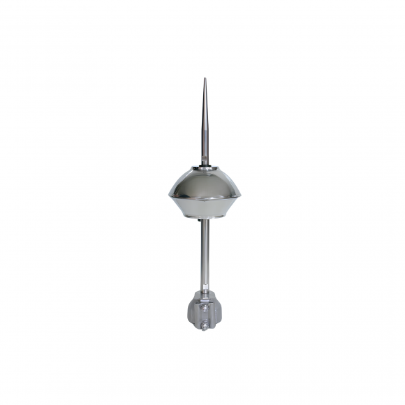
Air Termination Rods
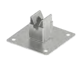
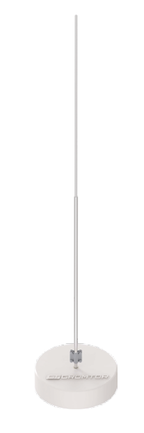 Concrete Base Air Terminal Ø16 mm
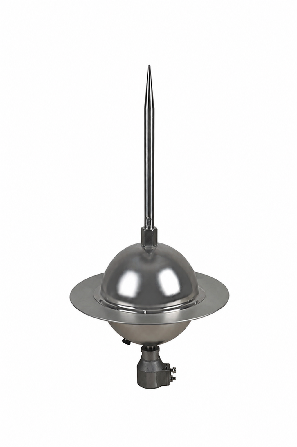
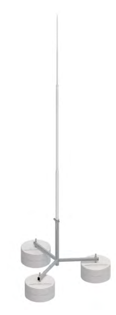 Air Termination Rod Ø40 mm on Tripod
View All →
Air Termination Rod Ø40 mm on Tripod
View All →

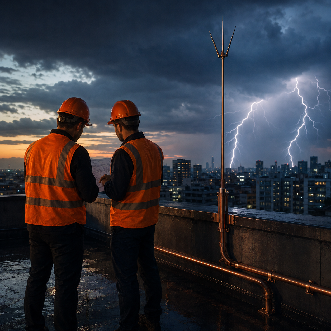
When lightning strikes a building directly, it produces currents exceeding 200,000 amperes and surges that rise in millionths of a second. The complete set of systems designed to carry this energy safely to earth without damaging the structure is called an external lightning protection system (LPS – Lightning Protection System). The aim is not to prevent lightning, but to determine in advance where it will strike and to route the current along a controlled path.
At Yılkomer every project begins with a risk assessment under the TS EN / IEC 62305 standard; we evaluate the geometry of the structure, its intended use, the density of people and equipment inside it and the lightning density data for the region together, and on that basis determine the protection level (LPL I–IV). The system design is then shaped around that level.
Following the site survey and risk assessment carried out in accordance with the standards, and depending on the suitability of the structure, the methods we apply are as follows:
This is the part that ensures lightning enters the structure at a predetermined point rather than at random. Rooftop air terminals, catenary wires, mesh (cage) conductors or isolated air termination masts carry out this task. The geometry of the air termination system is verified using the rolling sphere method: a sphere with a radius of 20 m for protection class I, 30 m for class II, 45 m for class III and 60 m for class IV is rolled over the structure, and every point the sphere touches is considered unprotected.
These are the conductors that carry the intercepted current from the roof down to earth. They are distributed symmetrically around the structure so that the current does not concentrate in a single path; typical spacings range from 10 m to 20 m depending on the protection class. The correct number of down conductors significantly reduces both the thermal load on the conductor cross-section and the risk of flashover to adjacent metal parts.
This is the most critical component in determining the performance of the system. It ensures the lightning current is dissipated into the earth quickly and at low impedance. Depending on the soil resistivity, ring earthing, deep-driven rod earthing or foundation earthing solutions are applied. In high-resistivity soils, conductivity-enhancing mineral backfills and exothermic welded connections are preferred.
Metal pipework, cable trays, lift guide rails, HVAC ducts and the protective conductors of the electrical installation inside the structure are all brought to a common potential. If this is not done, differences of thousands of volts arise between different points of the structure at the moment of the strike; this is where the risk to life and the damage to electronic equipment originate.
Key product groups used in external lightning protection systems
Concrete Base Air Terminal Ø16 mm
Air Termination Rod Ø40 mm on Tripod
View All →
Tell us about your project and we will get back to you shortly.
Your calculation is ready. Leave your contact details and your risk assessment will appear right away.
Your answers from the tool have been added to your request automatically. Leave your contact details and we will confirm the recommendation and prepare your quote.