2SS15N – RO
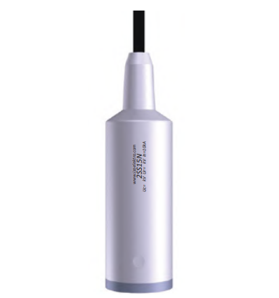
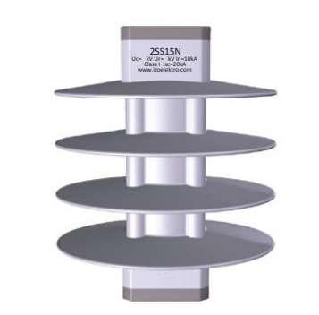
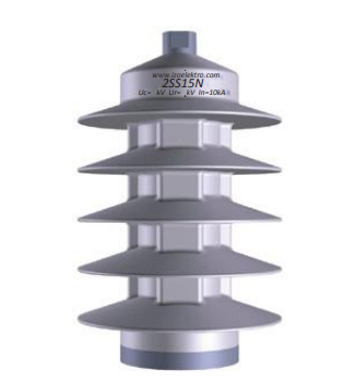
Metal oxide medium voltage surge arrester with silicone rubber housing. With a 700 mm fixed cable outlet from the top. IEC Class 1, Uc 3–40.5 kV, Ur 3.75–50.6 kV, In 10 kA, IP 67.
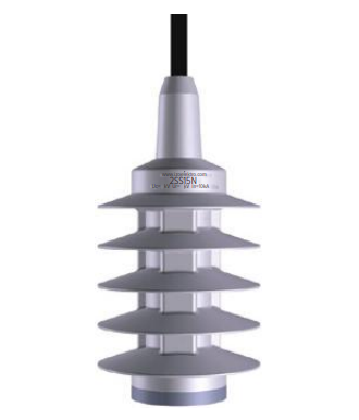
2SS15N-RO is a metal oxide surge arrester that provides protection against overvoltages and transient events in medium voltage networks up to 52 kV.
The varistor block is directly molded with silicone rubber.
The product is certified as Class 1 according to IEC 60099-4:2004 and IEC 60099-5 standards.
A distinctive feature of the RO housing form is the fixed cable at the upper end: a line connection cable with a length of 700 mm ± 10% extends from the top of the arrester. There is no upper terminal screw; the connection is made directly with this cable.
The lower end has an M12 × 20 grounding terminal.
HIGHLIGHTED FEATURES
- IEC Class 1 arrester
- 700 mm ± 10% fixed cable outlet from the top
- Varistor directly molded with silicone rubber
- IP 67 protection class
- High creepage distance (491–1211 mm)
- UV and chemical resistant, self-cleaning silicone surface
- −60 °C … +85 °C operating range
- Residual voltage value at seven different impulse currents
- 100% final inspection in the manufacturer's laboratory
- Each arrester is marked with an indelible measurement number
GENERAL TECHNICAL DATA
| Parameter | Value |
|---|---|
| Arrester type | 2SS15N |
| Commercial description (housing form) | RO |
| IEC class | 1 |
| Standard | IEC 60099-4:2004, IEC 60099-5 |
| Continuous operating voltage (Uc) | 3 – 40.5 kV |
| Rated voltage (Ur) | 3.75 – 50.6 kV |
| Nominal discharge current (In, 8/20 µs) | 10 kA |
| High impulse current (4/10 µs) | 100 kA |
| Short-circuit current (Isc) | 20 kA |
| Long-duration current (I2ms) | 250 A |
| Energy absorption capacity (long-duration, W2ms) | 2.8 kJ/kV·Uc |
| Energy absorption capacity (impulse, W4/10) | 4.8 kJ/kV·Uc |
| Cantilever strength (24 kV) | 300 Nm |
| Cantilever strength (36 kV) | 250 Nm |
| Vertical load (Fv) | 625 N |
| Protection class | IP 67 |
| Ambient temperature | −60 °C … +85 °C |
| Body material | Silicone rubber |
| Body color | Grey |
| Top connection | 700 mm ± 10% cable |
| Bottom terminal | M12 × 20 |
| Base diameter | Ø120 mm |
VOLTAGE LEVELS — ELECTRICAL
| Ur [kV] | Uc [kV] | 1/20 µs 5 kA | 1/20 µs 10 kA | 8/20 µs 5 kA | 8/20 µs 10 kA | 8/20 µs 20 kA | 30/60 µs 125 A | 30/60 µs 500 A | Upeak 1.2/50 µs | Urms 50 Hz 1 min |
|---|---|---|---|---|---|---|---|---|---|---|
| 3,75 | 3 | 8,55 | 9,65 | 7,18 | 8,78 | 9,60 | 7,35 | 7,85 | 62 | 25 |
| 5,00 | 4 | 12,80 | 14,20 | 11,25 | 12,92 | 14,15 | 9,63 | 10,16 | 62 | 25 |
| 7,50 | 6 | 21,35 | 23,85 | 17,95 | 21,70 | 23,75 | 16,98 | 18,01 | 62 | 25 |
| 10,00 | 8 | 25,60 | 28,40 | 26,12 | 25,84 | 28,30 | 19,26 | 20,32 | 98 | 35 |
| 12,50 | 10 | 34,15 | 38,05 | 29,00 | 34,62 | 37,90 | 26,61 | 28,17 | 98 | 35 |
| 15,00 | 12 | 38,40 | 42,60 | 33,15 | 38,96 | 42,45 | 28,89 | 30,48 | 98 | 35 |
| 17,50 | 14 | 46,95 | 52,25 | 39,98 | 47,54 | 52,05 | 36,24 | 38,33 | 125 | 55 |
| 20,00 | 16 | 51,20 | 56,80 | 44,10 | 51,68 | 56,60 | 38,52 | 40,64 | 125 | 55 |
| 22,50 | 18 | 59,75 | 66,45 | 51,26 | 60,46 | 66,20 | 45,87 | 48,49 | 125 | 55 |
| 25,00 | 20 | 64,00 | 71,00 | 55,45 | 64,60 | 70,75 | 48,15 | 50,80 | 135 | 60 |
| 26,25 | 21 | 67,55 | 77,10 | 58,93 | 67,95 | 76,25 | 52,15 | 54,55 | 135 | 60 |
| 27,50 | 22 | 72,55 | 80,65 | 63,00 | 73,38 | 80,35 | 55,50 | 58,65 | 135 | 60 |
| 30.00 ⁽¹⁾ | 24 | 76,80 | 85,20 | 66,15 | 75,98 | 84,90 | 57,78 | 60,96 | 135 | 60 |
| 30.00 ⁽²⁾ | 24 | 76,80 | 85,20 | 66,15 | 75,98 | 84,90 | 57,78 | 60,96 | 150 | 65 |
| 32,50 | 26 | 85,35 | 94,85 | 77,20 | 84,76 | 94,50 | 65,13 | 68,81 | 150 | 65 |
| 35,00 | 28 | 89,60 | 99,40 | 84,90 | 88,21 | 99,05 | 67,41 | 71,12 | 150 | 65 |
| 37,50 | 30 | 98,15 | 109,05 | 88,00 | 96,99 | 108,65 | 74,76 | 78,97 | 170 | 70 |
| 40,00 | 32 | 102,40 | 113,60 | 96,05 | 101,15 | 113,20 | 77,04 | 81,28 | 170 | 70 |
| 43,75 | 35 | 112,30 | 125,50 | 97,86 | 112,81 | 125,15 | 85,16 | 90,12 | 170 | 70 |
| 45.00 ⁽¹⁾ | 36 | 115,20 | 127,80 | 99,10 | 114,10 | 127,25 | 86,67 | 91,44 | 170 | 70 |
| 42,50 | 34 | 110,95 | 123,25 | 96,05 | 109,93 | 122,80 | 84,39 | 89,13 | 180 | 75 |
| 45.00 ⁽²⁾ | 36 | 115,20 | 127,80 | 99,10 | 114,10 | 127,35 | 86,67 | 91,44 | 180 | 75 |
| 50,60 | 40,5 | 125,76 | 136,35 | 114,89 | 129,78 | 146,25 | 96,12 | 101,35 | 180 | 75 |
Ures values are in kV.
VOLTAGE LEVELS — MECHANICAL
| Ur [kV] | AD [mm] | CD [mm] | A [mm] | B [mm] | H [mm] | N |
|---|---|---|---|---|---|---|
| 3,75 | 257 | 491 | 60 | 90 | 129 | 3 |
| 5,00 | 257 | 491 | 80 | 100 | 129 | 3 |
| 7,50 | 257 | 491 | 100 | 120 | 129 | 3 |
| 10,00 | 303 | 651 | 120 | 140 | 175 | 5 |
| 12,50 | 303 | 651 | 140 | 160 | 175 | 5 |
| 15,00 | 303 | 651 | 160 | 180 | 175 | 5 |
| 17,50 | 353 | 731 | 180 | 200 | 225 | 6 |
| 20,00 | 353 | 731 | 200 | 220 | 225 | 6 |
| 22,50 | 353 | 731 | 220 | 240 | 225 | 6 |
| 25,00 | 380 | 811 | 240 | 260 | 252 | 7 |
| 26,25 | 380 | 811 | 260 | 280 | 252 | 7 |
| 27,50 | 380 | 811 | 270 | 300 | 252 | 7 |
| 30.00 ⁽¹⁾ | 380 | 811 | 320 | 320 | 252 | 7 |
| 30.00 ⁽²⁾ | 427 | 891 | 320 | 320 | 299 | 8 |
| 32,50 | 427 | 891 | 340 | 340 | 299 | 8 |
| 35,00 | 427 | 891 | 360 | 360 | 299 | 8 |
| 37,50 | 480 | 1131 | 295 ⚠️ | 380 | 352 | 11 |
| 40,00 | 480 | 1131 | 380 | 400 | 352 | 11 |
| 43,75 | 480 | 1131 | 410 | 430 | 352 | 11 |
| 45.00 ⁽¹⁾ | 480 | 1131 | 420 | 440 | 352 | 11 |
| 42,50 | 517 | 1211 | 400 | 420 | 386 | 12 |
| 45.00 ⁽²⁾ | 517 | 1211 | 420 | 440 | 386 | 12 |
| 50,60 | 517 | 1211 | 450 | 470 | 386 | 12 |
⚠️ THREE SPECIAL CASES FOR R FORM ALSO APPLY HERE
1. Dual size option. There are two rows each for Ur = 30 kV and Ur = 45 kV:
| Ur | Option 1 | Option 2 |
|---|---|---|
| 30 kV | H 252 mm · 7 sheds · CD 811 | H 299 mm · 8 sheds · CD 891 |
| 45 kV | H 352 mm · 11 sheds · CD 1131 | H 386 mm · 12 sheds · CD 1211 |
2. Sorting disorder. 42.50 kV comes after 45.00 kV — the beginning of the second measurement group. Sort by voltage when entering the site.
3. In the row for Ur = 37.50 kV, the A value is still 295 mm. 360 mm in the lower stage, 380 mm in the upper stage.
- Indoor and outdoor installation
- Protection of electrical equipment
- Protection of compensation devices
- MV distribution networks (up to 52 kV)
- Applications requiring flexible line connection
- Substations and distribution panels
- Railways
- Mines
- IZOELEKTRO Product Catalog Download