The Concept of Grounding and Equipotential Bonding in Solar Systems
18 March 2016Protection of Prefabricated Buildings Against Overvoltage and Lightning
27 March 2016
1- GENERAL:
- Was the facility installed in accordance with its project?
- Was the underground cable installation carried out in accordance with the Cable Installation Procedures and Principles?
- Are there route marker plates (gabara) on the cable route? (To be used at a maximum of every 50 m, at all turns and road crossings)
- At building entrances, are the cables installed inside pipes? Is the space between the pipe and the cable filled with suitable material?
- Is there interior lighting in electrical installations?
- Are insect screens installed in ventilation openings?
- Is there a Danger of Death Warning Sign on all movable doors?
- Is there a Transformer Name plate on the door of each transformer center (transformer + cell + panel)?
- Are all doors opening outward and made of steel sheet?
- Are there automatic battery-powered Emergency Lamps in every section of transformer centers?
- Is there a Fire Extinguisher (CO2) within 25 m of each transformer center?
- Is there a First Aid Kit within 25 m of each transformer center?
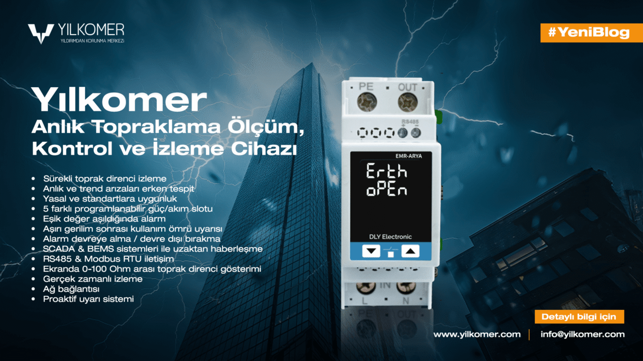
- Is the operating grounding below 1 ohm and the protective grounding below 1 ohm?
- At the PV plant entrance, fences, structures, concrete kiosks, inverters, cable trays, etc., are the warning signs specified in the annex used?
- Cables must be labeled.

2- TRANSFORMER COMPARTMENT:
- Are the transformer nameplate values compatible with the project?
- Is there body grounding of the transformer at two points, on the cover and at the base?
- Is there a chain and Danger of Death Warning Sign at the entrance of the transformer compartment?
- Is there insulation on LV and MV bushings to protect against contact?
- Are the transformer wheels fixed with wedges?
- Is all metal equipment in the transformer compartment grounded?
- Is there at least 60 cm distance between the transformer and the walls? (Not applicable for concrete kiosks)
- Are MV cable cross-sections compatible with the project?
3- MV CONTROL COMPARTMENT
- Is the installation of the cells carried out in accordance with the project?
- Do MV cells have body grounding?
- Is all metal equipment in the MV control compartment grounded?
- Is the distance between the cells and the rear wall equal to or greater than 10 cm?
- Are MV gloves, insulating mats, and stools available?
- Is there a BAR-24 separately for each MV Control compartment?
- Is there a Fire Extinguisher (CO2) within a maximum of 25 m of each MV Control Compartment?
- Is the top of the cable duct in the cell compartment covered with galvanized sheet metal?
- Is there a single-line diagram in the MV Control Compartment?
- Are there plates on MV cells indicating input/output information?
- Is there a First Aid Instruction for electrical accidents?
- When the power goes out, the autoproducer breaker must open.
- When the power is restored, the autoproducer breaker must close.
- When the autoproducer breaker is opened manually, it must not reclose automatically.

4- LV PANEL and FIELD COMBINER PANEL
- Are the nameplate values of the LV Panel compatible with the project?
- Does the LV Panel have body grounding?
- Is all metal equipment in the LV panel compartment grounded?
- Are the ratings of the MCCB and outgoing fuses in the LV Panel compatible with the project?
- In the LV panel, when power is cut from MV, the motorized MCCB must open (if specified in the project).
- In the LV panel, when power is supplied from MV, the motorized MCCB must close (if specified in the project).
- When opened manually in the LV panel, the motorized MCCB must not reclose (if specified in the project).
- When the motorized MCCB is opened manually, there must be no energy on the lower busbars of the MCCB.
- Are measuring devices connected before the MCCB? (Do they measure energy when the MCCB is open (0)?)
- Are MV cable cross-sections compatible with the project?
- In the field panel, are DC fuses correct and are RCD values correct? Are short-circuit breaking capacities correct?
- LV panels must have an Emergency Trip Button that directly trips the transformer protection cell.

Enpoc solar power plant lightning and surge protection
5- INVERTER
- The manufacturing date of panels and inverters must not exceed 5 years. Serial numbers of inverters and panels are important.
- Inverter power ratings and configurations must comply with the project.
- When grid power is cut, a test must be performed to verify that the inverters stop operating.
- The presence of DC fuses and surge arresters inside the inverter must be checked according to the project.
6- SOLAR PANELS
- The manufacturing date of panels and inverters must not exceed 5 years. Serial numbers of inverters and panels are important.
- Does it comply with the site layout plan? Are panel placements and quantities correct? Are panel power ratings correct?
- Special attention must be paid to the front-rear height, tilt angles, and spacing between panels to ensure compliance with the project.
7- FIELD APPLICATIONS: CONSTRUCTION–STRUCTURE–FENCE–CABLE TRAY
- Installation must be carried out in accordance with the approved construction project.
- Special attention must be paid to the front-rear height, tilt angles, and spacing between panels to ensure compliance with the project.
- Warning signs specified in the annex must be used frequently on fences, cable trays, and piles.
- There must be barbed wire under the fence.
- Fire extinguishers must be available at various points in the field (especially near field panels).
- Concrete kiosks and field combiner panel access roads must be suitable for vehicle access (gravel/paving/asphalt/stabilized, etc.).
- There must be no grass, trees, or bushes in the field.
8- GROUNDING–LIGHTNING PROTECTION –LV SURGE ARRESTER
- Grounding must be carried out in accordance with the approved grounding project.
- When using Cu and Al during grounding, bimetal must be used at connection points and precautions must be taken against oxidation.
- Even if not included in the project, all metal equipment in the facility (doors, fences, etc.) must be grounded.
- Both operating and protective grounding must be below 1 ohm.
- A report proving that grounding measurements were carried out by an authorized engineer, authorization documents, calibration certificates, must be submitted as an annex to the provisional acceptance report.
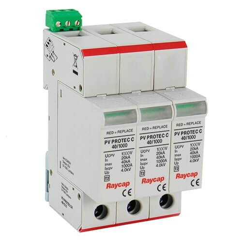
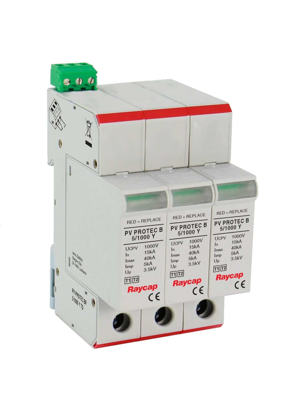
- Were Class B+C Surge Arresters used on AC and DC lines and Class D Surge Arresters on communication lines?
- Was the External Lightning Protection System bonded to equipotential? Were spark gap arresters used?
- Was the External Lightning Protection System designed in accordance with IEC 62305? Are the air terminals used anticorrosive?
- Were measurements of the External Lightning Protection System carried out in accordance with IEC standards?
- Was equipotential bonding achieved in the facility? Does the resistance difference across the facility exceed 0.2 ohms?

