
Einsatz von Niederspannungs-Überspannungsschutzgeräten in Sicherheits- und Automationssystemen
3 January 2015
The Path Followed by a Lightning Strike Within Our Facility
3 January 2015
Grounding in Solar Power Plants: In order to prevent photovoltaic systems from being damaged by sudden overvoltages and lightning strikes, protecting solar systems within the scope of the IEC 62305-5 Standard is a mandatory requirement. Ensuring that systems planned as long-term investments can generate energy at the desired efficiency requires implementing all necessary protection measures, which is often one of the most neglected issues by investors. In this context, we have summarized below the key points to be considered regarding the protection and grounding of PV systems against lightning.
General Principles in the Protection of Solar Power Plants
Within the scope of the relevant standard, the importance of four-level protection is emphasized. To ensure that PV facilities are not damaged by lightning and surge-related effects, the integration of the following four systems is essential.
1-External Lightning Protection System: Within the scope of the standard, appropriate protection angles should be created according to the rolling sphere method based on passive systems. The system designed as a result of risk calculations should aim to protect both the site and PV system equipment from the direct effects of lightning strikes.
2-Internal Lightning Protection System: The use of internal lightning protection systems on AC-DC and coaxial lines will prevent the system from burning out and becoming inoperative during lightning and sudden surge events.
3-Equipotential Bonding System: Ensuring equipotential bonding throughout the facility eliminates resistance differences and prevents coupling effects that may occur as a result.
4-Grounding System: Foundation and functional grounding systems established at and around the facility will ensure long-term protection of the installation against electrical adverse effects.

Grounding of solar power plants requires expertise and experience.
Risk analysis is essential for the selection of products to be used and for the design and engineering of the system to be installed.
First, the lightning activity ‘E’ of the structure to be protected shall be calculated. Based on the calculated ‘E’ coefficient, the protection level must be determined from the relevant table.
For both rooftop and ground-mounted installations, integration of the four systems mentioned above is critical. In accordance with the TSE EN 62305 standard, all PV installations must ensure protection of panel areas in terms of human safety and electrical system security. Based on the risk analysis, appropriate air termination systems should be designed considering direct lightning strike risks to PV installations. Special attention must be paid to ensuring that lightning down conductors passing near facility equipment are insulated (tested against lightning strikes). Otherwise, coupling effects may damage the system. External lightning protection system components to be used must have successfully passed tests against 100 kA lightning impulses.
Construction of the Grounding System
Grounding must be implemented at the facility to ensure the electrical safety of the systems. Grounding systems and equipment should be designed in accordance with the Ministry of Energy Grounding Regulation, TS HD 60364-5-54 and TSE EN 50164 standards.
For foundation grounding and functional and operational grounding, the key considerations are the quality of materials used and long-term resistance against corrosion. For example, for a 30×3.5 grounding strip, a minimum coating thickness of 70 microns is specified under TSE EN 50164. The grounding project must be designed by an expert engineer in accordance with site conditions. The use of corrosion tape and bimetal compatibility are critical. Inverters and AC sections of equipment installed on site must be grounded. Additional precautions must be taken for grounding equipment mounted on structures.
In ground-mounted installations, depending on suitability, mesh networks under panels with cell sizes not exceeding 20×20 m should be combined with surrounding ring conductors, and this universal grounding should reach every structure and system component via equipotential bars. All calculations must be designed by a qualified engineer.
Equipotential Bonding Conductor
Equipotential bonding is a protective measure applied against the possibility of electrical installations having a higher potential relative to ground in the event of a fault. When implemented, the potential difference between ground and other parts is eliminated, reducing electric shock risk to a minimum. Relevant parts of the installation are categorized as exposed conductive parts or extraneous conductive parts.
In many PV systems, such exposed or extraneous conductive parts are not present; therefore, equipotential bonding conductors are generally not required. If equipotential bonding conductors are necessary, the decision tree below is applied. On the DC side of PV installations, double or reinforced insulation must be applied during the design stage. Accordingly, system components are insulated and additional protective equipotential bonding is not required.

An insulated down conductor is essential for a correct and safe system.
All equipment within the facility must be connected to local equipotential bars via equipotential bonding conductors. The external lightning protection system must also be connected to this bonding conductor. However, connections to equipotential bars within the facility must be made via spark gap surge arresters to ensure that potential impulses are immediately suppressed.
System Grounding (DC Conductor Grounding)
- DC grounding scenarios for PV generators can be summarized as follows:
- No ground connection.
- Physical grounding of positive and negative conductors.
- Center-tapped connection with or without grounding.
- High-impedance grounding of positive or negative conductors (for functional purposes).
Manufacturer instructions for PV modules and equipment forming the PV generator must be considered to ensure appropriate grounding arrangements. Grounding a current-carrying DC conductor is not recommended. However, if AC and DC sides are properly separated, grounding one of the energized conductors may be permitted. Where functional grounding is required and possible, it should preferably be implemented via high impedance rather than direct connection.
The designer must verify that the inverter is suitable for DC grounding. Transformerless inverters are not suitable, and grounded DC conductors may interfere with integrated DC insulation monitoring systems. Therefore, if DC conductor grounding is required, it must be implemented within the inverter in accordance with the inverter manufacturer’s approval and guidance.
The inverter is the backbone of solar power plants and must be protected against lightning and surge events.
When PV systems are connected to inverters, IEC 62109-2 defines grounding requirements based on inverter topology and grounding arrangements. These include minimum inverter insulation requirements, generator insulation resistance measurement requirements, and residual current detection and ground fault alarm requirements.
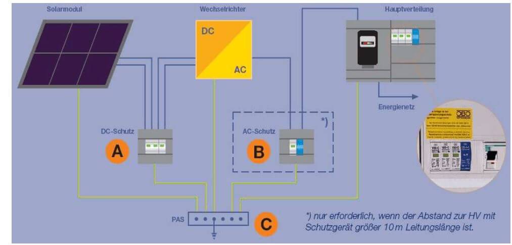
Surge Protection Measures
In accordance with the TSE EN 62305 standard, internal lightning protection systems must be used to protect systems against sudden overvoltages. While external lightning protection systems provide physical protection, surge protection devices electrically protect the installation and prevent system components from becoming inoperative. AC-DC and data lines within the facility must be protected against lightning and sudden overvoltages.
Protection of AC Lines
- Products integrated with 10/350 and 8/20 waveforms shall be used in a graded protection approach (use of B+C class products is recommended).
- As Type 1 protection devices, products with Carbon Ring (Spark Gap) technology, without varistor technology, capable of minimum 50 kA per phase, operating before Class C devices, and suitable for -40°C to +85°C with IP20 protection are recommended.
- Type 2 protection devices shall operate independently of Class B and be activated after Class B. Products with 8/20 waveform extinguishing capacity of 40 kA, voltage protection level >1.3 kV, response time max 25 ns, and temperature range -40°C to +80°C should be selected.
Protection of DC Lines
- Products integrated with 10/350 and 8/20 waveforms shall be used in DC lines as graded protection (B+C class products are recommended).
- Operating temperature range must be -40°C to +80°C with IP20 protection.
- Positive, negative, or positive-negative grounding connections must be provided.
Protection of Data/CAT Lines
- All data and CAT communication lines should be protected according to their characteristic properties.
- Use of Class D products tested according to the 8/20 waveform is recommended.
